
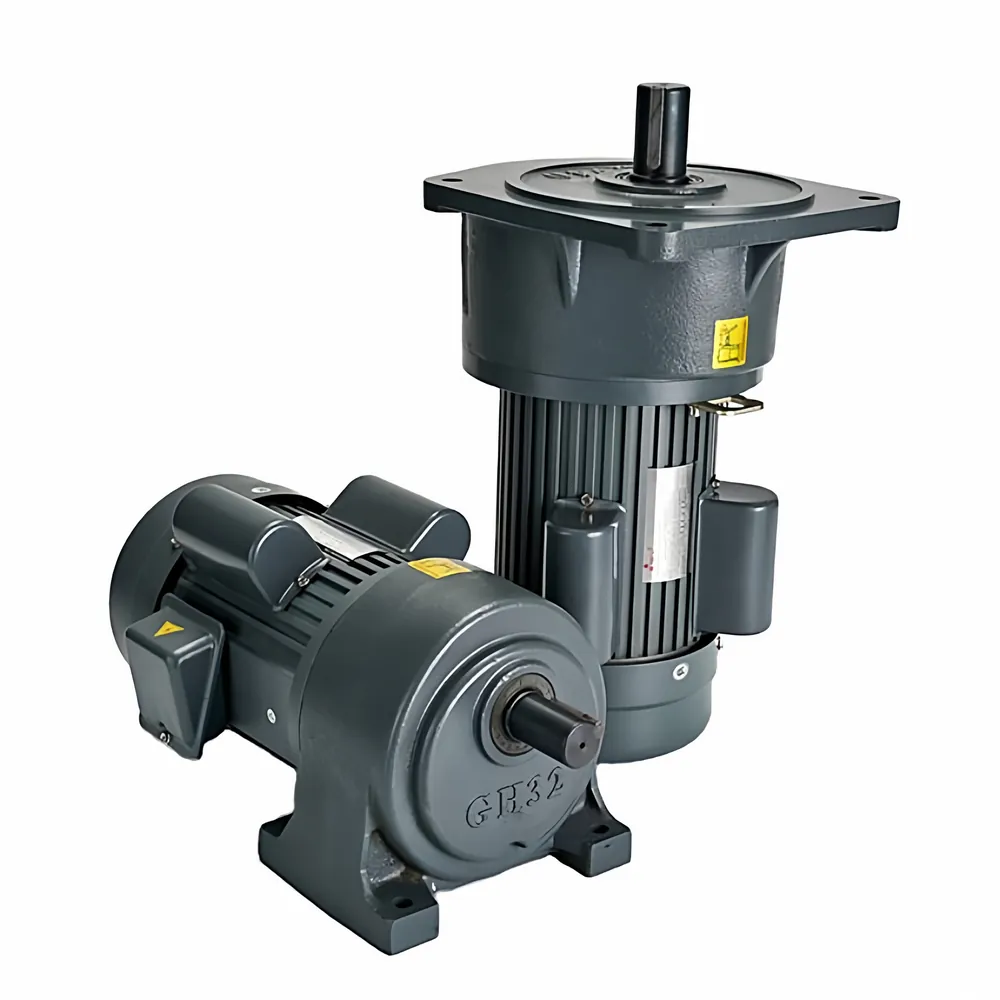
An AC geared motor combines an electric motor and a reduction gearbox in one drive package. The gearbox lowers speed and increases usable output torque, while the motor supplies the input power. Correct selection starts with the machine duty: conveyor speed, drum or sprocket size, load, starts per hour, operating time and mounting position.
1. Define the Required Output Speed
Measure or calculate the driven shaft speed first. The preliminary reduction ratio is:
Example assumption: a four-pole motor runs at 1,400 rpm under the local supply conditions and the machine needs 70 rpm.
i = 1,400 ÷ 70 = 20
A nominal 20:1 ratio is the starting point. Actual output speed depends on the motor's loaded speed and the available gearbox ratio.
For conveyors, belt speed must also be converted into drive-shaft speed. Our conveyor gearbox application page explains the application data needed for this step.
2. Calculate Torque, Then Apply Service Factor
The motor's approximate rated torque can be calculated from power and speed:
Example assumption: 0.75 kW motor at 1,400 rpm.
Motor torque = 9550 × 0.75 ÷ 1,400 ≈ 5.12 N·m
Estimated gearbox output torque = motor torque × ratio × assumed efficiency.
At 20:1 and an illustrative 85% efficiency: 5.12 × 20 × 0.85 ≈ 87 N·m.
The gearbox must also handle starts, shocks and long operating hours. If the calculated load torque is 60 N·m and the application service factor is 1.4, the minimum comparison torque is:
60 × 1.4 = 84 N·m
See the service-factor selection guide for the same duty principles applied to industrial reducers.
3. Match the SMK GH/GV Model Range
| Foot-mounted | Flange-mounted | Output shaft diameter |
|---|---|---|
| GH18 | GV18 | 18 mm |
| GH22 | GV22 | 22 mm |
| GH28 | GV28 | 28 mm |
| GH32 | GV32 | 32 mm |
| GH40 | GV40 | 40 mm |
| GH50 | GV50 | 50 mm |
The documented power range is 0.1–3.7 kW. Standard ratios are 3–200; ratios 250–1800 are available through combined arrangements. GH models are foot-mounted and GV models are flange-mounted. Review the full SMK GH/GV coaxial geared motor specifications.
4. Confirm Voltage, Frequency and Motor Type
Supply voltage and frequency affect motor winding, speed and current. State the operating country and supply—for example, 220/380 V at 50 Hz—rather than ordering only by kW. If the drive uses a VFD, identify the speed range and cooling conditions. The SMK electric motor page lists the available motor platform, while the final winding must be confirmed for the order.
5. Choose GH or GV Mounting
- GH foot-mounted: suitable when the gearbox sits on a rigid machine base.
- GV flange-mounted: suitable for direct flange support at the driven machine.
Confirm the installation direction, available space, shaft orientation and whether the load creates significant radial or axial force. Misalignment can shorten bearing and seal life even when the motor power is correct.
6. Decide Whether a Brake Is Required
A brake may be required for indexing, holding a suspended load, emergency stopping or preventing unwanted movement after power is removed. Do not assume gearbox resistance is a safety brake. State the required stopping time, holding torque, duty and power-off behavior.
Selection Checklist for an RFQ
- Application and driven-machine type
- Motor power, voltage, frequency and phase
- Required output speed or ratio
- Continuous and peak load torque
- Operating hours, starts per hour and shock level
- Foot or flange mounting and shaft direction
- Required output shaft diameter and external load
- Brake, VFD, protection and ambient conditions
Conclusion
A reliable AC geared motor selection follows a clear sequence: required output speed → ratio → load torque → service factor → available GH/GV model → thermal and mechanical verification. Use calculated values to narrow the options, then confirm the exact combination for the application.