
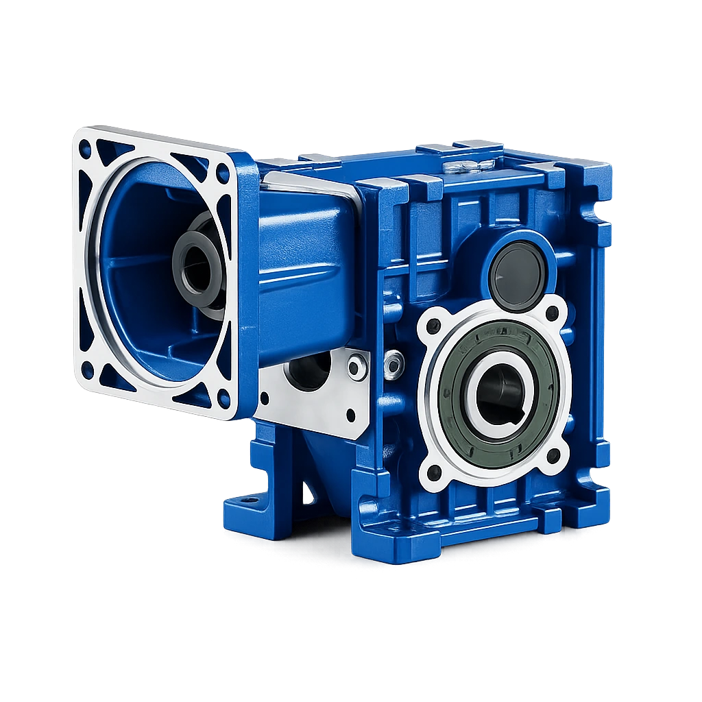
KM Series Hypoid Gear Reducer
Components
1. Housing:
Aluminium alloy housing for KM050–KM090.
Gray cast iron housing for KM110.
2. Gears:
Helical and hypoid bevel gear set manufactured from 20CrMnTi steel, with carburizing and nitriding treatment and approximately 0.3–0.6 mm remaining carburized layer after precision grinding.
Gear hardness: 58–62 HRC.
3. Input Configurations:
Compatible with electric motors including AC motor, brake motor, DC motor and servo motor.
Hollow shaft input with IEC flange (B5/B14).
Hollow shaft input with NEMA flange.
Hollow shaft input with servo motor flange.
Solid shaft input.
4. Output Configurations:
Keyed hollow shaft output.
Hollow shaft with output flange.
Plug-in solid shaft output.
5. Spare Parts:
Output shaft, output flange, torque arm and dust cover.
6. Gearbox Painting:
Aluminium alloy gearbox with shot blasting, anticorrosion treatment and phosphating, painted in RAL 5010 blue or RAL 7035 silver gray.
Models
KM040–KM110
Features
- Compact right-angle hypoid transmission for industrial machinery.
- Rated efficiency above 90% under applicable operating conditions.
- Approximately 10%–40% efficiency improvement compared with conventional RV series worm gearboxes, depending on ratio and operating point.
- Modular design with multiple motor, flange and shaft combinations.
- Mounting dimensions are compatible with corresponding RV series sizes except KM050 and RV050; confirm the certified drawing before replacement.
- High-efficiency KM series units can replace RV series reducers in a wide range of suitable applications after dimensional and duty confirmation.
Parameters
| Models | Transmission Stage | Nominal Ratio | Output Speed (n2)* | Max. Torque | Input Shaft Dia. | Output Hole Dia. | Output Shaft Dia. |
|---|---|---|---|---|---|---|---|
| KM050 | 3 Stage | 50–300 | 4.8–27 | 130 N·m | Φ11 | Φ20, Φ25 | Φ25 |
| 2 Stage | 7.5–60 | 24–181 | 130 N·m | Φ11 | |||
| KM063 | 3 Stage | 50–300 | 4.6–27 | 200 N·m | Φ11 | Φ25, Φ28 | Φ25 |
| 2 Stage | 7.5–60 | 23–184 | 200 N·m | Φ14 | |||
| KM075 | 3 Stage | 50–300 | 4.7–28 | 350 N·m | Φ14 | Φ28, Φ30, Φ35 | Φ28 |
| 2 Stage | 7.5–60 | 24–187 | 350 N·m | Φ16 | |||
| KM090 | 3 Stage | 50–300 | 4.7–28 | 500 N·m | Φ14 | Φ35, Φ38 | Φ35 |
| 2 Stage | 7.5–60 | 24–187 | 500 N·m | Φ19 | |||
| KM110 | 3 Stage | 50–300 | 4.7–27 | 750 N·m | Φ19 | Φ40, Φ42 | Φ42 |
| 2 Stage | 7.5–60 | 24–187 | 750 N·m | Φ24 |
3 Stage Ratio: 300, 250, 200, 150, 125, 100, 75, 60, 50
2 Stage Ratio: 60, 50, 40, 30, 25, 20, 15, 12.5, 10, 7.5
Installation
Foot mounted
Flange mounted
Lubrication
Grease lubrication
Oil-bath and splash lubrication
Cooling
Natural cooling
Please leave your detailed requirements and contact information. We will reply ASAP.
Compare and source with factory support
For a complete drive decision, compare efficiency and installation needs with the adjacent gearbox family, then confirm ratio, motor interface and quantity with the SMK team.
KM Hypoid Gear Reducer FAQ
Common questions about KM Series sizes, ratios, mounting and selection.
What KM hypoid gearbox sizes are available?
The KM Series listed on this page covers KM040 through KM110. Housing material and shaft dimensions vary by size and selected configuration.
What power and ratio range does the KM Series cover?
The listed motor power range is 0.12 to 5.5 kW and the nominal ratio range is 7.5 to 300. Maximum torque varies by model and reaches up to 750 N·m in the listed range.
Which mounting and output configurations are available?
Foot-mounted and flange-mounted arrangements are available. Hollow-shaft, output-flange and solid-shaft options depend on the selected model and must be confirmed before ordering.
When should I choose a hypoid reducer instead of a worm reducer?
A hypoid reducer can be considered when higher efficiency and continuous-duty performance are priorities. The final choice should also compare ratio, output torque, shaft arrangement, mounting space, duty and budget.